Enhanced integrated electrode solution
A range of enhancements has been added to the Delcam Electrode integrated solution for the design, machining and inspection of electrodes.
The new version includes support for burn-vector electrodes, automated machining of electrode frames, batch processing of multiple machining projects and faster generation of electrode drawings.
 Delcam Electrode also benefits from a number of options introduced into Delcam’s PowerSHAPE design software which provides the CAD element of the overall solution.
Burn-vector or side-sparking electrodes are used to spark undercuts within moulds, including those needed for submarine gates, or to avoid any possibility of a collision when sparking the base of a deep rib or similar feature.
They use an arbitrary axis for their operation, rather than being aligned with the principal axes.
Delcam Electrode now allows these electrodes to be designed and used with the same quick and easy wizard-based process available for conventional electrodes. The electrode action can be simulated in the software and the final design passed to the PowerMILL CAM system for machining in the same way as standard electrodes.
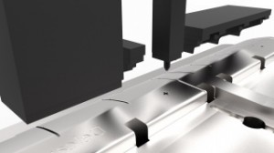
Electrode frames are used to provide the basis for machining and inspection datums. Delcam Electrode now allows these areas to be modelled and then coloured separately from the electrode blank.
This makes it easy for them to be identified in PowerMILL for automated manufacture using a specific template. The burn region, extension faces and clearance faces were already able to be displayed and machined with separate colours in this way.
The ability to automate programming within PowerMILL as part of the electrode solution does save considerable time for the user. However, when machining a large number of electrodes, it is inefficient to wait for toolpaths to be calculated on each individual project.
To overcome this problem, the option to use batch processing of multiple projects has been introduced within the electrode machining wizard.
The user now simply allocates one machining template in PowerMILL to a series of electrodes if the designs are similar, or applies the appropriate template to each example if they differ significantly in size or style. Processing the toolpaths starts as soon as the first project is loaded.
Subsequent projects are displayed in a list, with calculations beginning on the next item in the list automatically.
At any stage, the user can move items up and down the list, depending on the urgency of the various tasks.
If the calculations for a particular electrode cannot be completed, for example, if the software detects a collision, the problem is recorded and PowerMILL moves on to the next item automatically.
Thus, a long series of calculations can be left to run overnight if necessary. Alternatively, the complete series of projects can be collected into a folder and moved to a second computer for calculation, while the user carries on with other tasks on his main computer.
The ability to generate customised drawings automatically is another important benefit of the electrode solution.
This has been enhanced so that information generated while the user progresses through the electrode-design wizard, such as the project name or the different spark gaps to be applied, is used to fill in details for the drawings immediately. Generation of the drawings when the design is complete becomes much faster as a result.
All of the direct modelling enhancements to PowerSHAPE help to speed the creation of the electrode design.
Of particular benefit are the ‘replace-face’ command, which ensures extensions are at the same height when merging electrodes to be machined from a single blank, and the ‘solid-split command’, which makes it easier to divide unwanted material away from the electrode to create a simpler shape for machining.


